
Thursday, February 14, 2008
Power Supply Failure Alarm
Thursday, February 7, 2008
Electronic Scoring Game

You can play this game alone or with your friends. The circuit comprises a timer IC, two decade counters and a display driver along with a 7-segment display. The game is simple. As stated above, it is a scoring game and the competitor who scores 100 points rapidly (in short steps) is the winner. For scoring, one has the option of pressing either switch S2 or S3. Switch S2, when pressed, makes the counter count in the forward direction, while switch S3 helps to count downwards. Before starting a fresh game, and for that matter even a fresh move, you must press switch S1 to reset the circuit. Thereafter, press any of the two switches, i.e. S2 or S3. On pressing switch S2 or S3, the counter’s BCD outputs change very rapidly and when you release the switch, the last number remains latched at the output of IC2. The latched BCD number is input to BCD to 7-segment decoder/driver IC3 which drives a common-anode display DIS1. However, you can read this number only when you press switch S4. The sequence of operations for playing the game between, say two players ‘X’ and ‘Y’, is summarised below:
1. Player ‘X’ starts by momentary pressing of reset switch S1 followed by pressing and releasing of either switch S2 or S3. Thereafter he presses switch S4 to read the display (score) and notes down this number (say X1) manually.
2. Player ‘Y’ also starts by momentary pressing of switch S1 followed by pressing of switch S2 or S3 and then notes down his score (say Y1), after pressing switch S4, exactly in the same fashion as done by the first player.
3. Player ‘X’ again presses switch S1 and repeats the steps shown in step 1 above and notes down his new score (say, X2). He adds up this score to his previous score. The same procedure is repeated by player ‘Y’ in his turn.
4. The game carries on until the score attained by one of the two players totals up to or exceeds 100, to be declared as the winner.
Several players can participate in this game, with each getting a chance to score during his own turn. The assembly can be done using a multipurpose board. Fix the display (LEDs and 7-segment display) on top of the cabinet along with the three switches. The supply voltage for the circuit is 5V
Monday, January 28, 2008
half wave rectifier
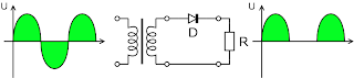
A half wave rectifier is a special case of a clipper. In half wave rectification, either the positive or negative half of the AC wave is passed easily, while the other half is blocked, depending on the polarity of the rectifier. Because only one half of the input waveform reaches the output, it is very inefficient if used for power transfer. Half-wave rectification can be achieved with a single diode in a one phase supply
Rectifier
A rectifier is an electrical device that converts alternating current to direct current or at least to current with only positive value, a process known as rectification. Rectifiers are used as components of power supplies and as detectors of radio signals. Rectifiers may be made of solid state diodes, vacuum tube diodes, mercury arc valves, and other components.
A circuit which performs the opposite function (converting DC to AC) is known as an inverter.
When only one diode is used to rectify AC (by blocking the negative or positive portion of the waveform), the difference between the term diode and the term rectifier is merely one of usage, i.e., the term rectifier describes a diode that is being used to convert AC to DC. Almost all rectifiers comprise a number of diodes in a specific arrangement for more efficiently converting AC to DC than is possible with only one diode. Before the development of silicon semiconductor rectifiers, vacuum tube diodes and copper(I) oxide or selenium rectifier stacks were used.
Early radio receivers, called crystal radios, used a "cat's whisker" of fine wire pressing on a crystal of galena (lead sulfide) to serve as a point-contact rectifier or "crystal detector". In gas heating systems flame rectification can be used to detect a flame. Two metal electrodes in the outer layer of the flame provide a current path and rectification of an applied alternating voltage, but only while the flame is present
Subscribe to:
Posts (Atom)

